Image-guided surgery (IGS) systems have brought both the raw and processed images into the operating room (OR) and clarified the relationship between the images and anatomy. Intra-operative MRI (iMRI) systems have integrated all of these functions and elevated the timeliness of the information to a new level, enabling intra-operative updates of all information for burr hole alignment, craniotomy extent reduction, resection control, eloquent tissue avoidance, subsurface visualization, and complication detection. Various iMRI systems have been designed to satisfy the surgical imperatives and provide timely, quality images while preserving surgical workflow. This article will examine the ability of the various systems to meet these objectives, consider other factors that influence the acceptance of the systems, and examine trends that indicate their utility. Developments in complementary systems and technology have accompanied the advances in iMRI system design, but these developments will not be discussed here. Readers interested in a broader review and analysis are invited to consult recently published general iMRI system reviews,1,2 along with general MR safety guidelines3,4 and iMRI-specific safety discussions.5,6
The relative characteristics of iMRI systems designed specifically to meet this developing surgical need are compared with those of diagnostic systems with ‘add-on’ iMRI packages in Table 1. The physics of MR dictate that optimal IQ is achieved when the magnet, gradients, and radiofrequency (RF) coils can surround the patient and get as close as possible to the anatomy of interest. This directly competes with the surgical access requirement, thus explaining the contrast between those features in Table 1. Some designs provided both access and IQ but at different times, which then made the ease and speed of transition between surgery and imaging a prime design objective. All designs provide some type of MR-compatible head frame for patient fixation.
Specialized Systems
Three different specialized systems were designed with a vertical gap and low field magnets (0.12–0.5 Tesla (T)) with imaging capabilities less than that found on standard 1.5T cylindrical superconducting systems. The systems had widely differing siting requirements, which influenced their clinical acceptance.Historical Systems
The 0.5T ‘double donut’ design (GE Healthcare, Waukesha, Wisconsin) and the one-of-a-kind 0.2T vertical gap system at the University of Toronto are no longer available. Space considerations preclude a discussion of these systems, but interested readers may want to consult references 7 and 8.
Compact Intra-operative Magnetic Resonance Imaging System
The PoleStar® (Medtronic Navigation Israel Inc., Yokneam, Israel), first introduced in 2000, uses 0.12T and now also uses 0.15T U-arm shaped permanent magnets. The scanner weight of ~600kg eliminates the floor reinforcement requirement and an optional local, portable, expandable RF shield can eliminate the room-shielding requirement, thus simplifying siting. When idle, the scanner and portable shield are stored in a magnet-shielding cabinet (MSC) adjacent to the OR, allowing the OR with its resident navigation system to be used for other surgeries.
The magnet is positioned underneath the operating table during the surgical procedure, allowing standard surgical workflow and patient access, then raised for imaging using the gantry’s motion control unit, with a typical surgery–scan–surgery cycle taking only five to 20 minutes. Its low magnetic field (LMF) allows the use of most conventional surgical tools. LMF-strength scanners have lower IQ; therefore, flexible, single-use, receive coils with perpatient tuning are positioned directly on the patient’s skull to maximize acquisition of the available signal.
The scanner is integrated with a surgical navigation workstation (StealthStation®, Medtronic Inc., Louisville, Colorado), including an optical instrument tracking system that also tracks the magnet, allowing automatic registrations between the patient anatomy and image data. The scanner and navigation system are operated by the OR staff, eliminating the need for radiology staff. The scanner can acquire four common sequences used for surgical navigation, imaging updates, and resection control. Sophisticated pre-operative imaging protocols (functional, diffusion tensor imaging (DTI), etc.) can be fused with intra-operative data in the surgical navigation workstation but cannot be updated intra-operatively.
Enhanced Diagnostic Systems
The enhanced diagnostic systems use both horizontal gap and cylindrical bore superconducting magnets. The surgical location is either just outside the magnet with MR-compatible instruments or beyond the 5 Gauss line with standard instruments. The horizontal gap systems not only employ patient motion for surgical patient access, but also provide interactive patient access for interventional procedures, with the accompanying IQ penalty of their lower field. The closed bore systems provide patient access through motion, either moving the magnet to change the surgical environment to an imaging environment or moving the patient between an imaging location and the surgical locations.
Horizontal Gap Systems
0.3 Tesla Horizontal Gap System
In 1998, a 0.3T vertical field open scanner (Hitachi AIRIS II, Kashiwa, Chiba, Japan) was installed for both operative and diagnostic procedures to provide a cost-effective utilization of the scanner.9 The biplanar magnet structure has a generally open configuration with 43cm between the magnet poles, requiring re-positioning for patients in the lateral decubitus position. A redesigned user interface and MR-compatible display/mouse provide in-room scanner control. The scanner tabletop’s 120° rotation combined with the tabletop’s translation moves the patient’s head beyond the 5 Gauss line, and the floor behind the magnet has been lowered to facilitate surgical access. The patient handling system supported interactive procedures in the magnet and surgical procedures immediately adjacent to it.
Horizontal Gap Systems—Version 2
An MR–OR patient table that can pivot on a pedestal in front of the magnet (Magnetom Open Viva, Siemens Medical Solutions, Erlangen, Germany) can be locked at several positions to locate the patient’s head beyond the 5 Gauss line. In these positions the table has variable height, left/right tilt, or Trendelenberg/reverse Trendelenberg. For imaging, the table is returned to a horizontal position, swivelled back in front of the magnet, and moved into the bore. The patient transfer to and from the magnet takes only a few minutes and the anesthesia equipment remains fixed. This design permanently locates the scanner in the OR, impeding the use of the scanner for conventional diagnostic imaging or the use of the OR for non-MR-guided procedures.10 Cylindrical Bore Systems
Rotating Table Version
The same rotating-table concept was applied to cylindrical magnets with 60cm and then 70cm bores (Magnetom Symphony, Magnetom Espree, Siemens Medical Solutions, Erlangen, Germany),11 providing high-field options not previously available. The larger bore diameter significantly enhances patient-positioning options, particularly for broad-shouldered patients in a lateral decubitus position. In 60cm bore systems these patients had been re-positioned for imaging or could not be accommodated at all. An eightchannel array coil was integrated into the MR-compatible head clamp. The coil’s superior IQ supports advanced neuroimaging applications such as fMRI12,13 and fiber tracking with DTI.14–16
Ceiling-rail-mounted Magnet System
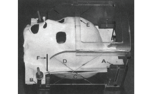
The 70cm bore magnet is also the platform for a system that brings the magnet to the OR on overhead rails (IMRISneuro, IMRIS Inc., Winnipeg, Canada),17–20 providing 1.5T IQ with zero patient or anesthesiology movement, thus eliminating any safety concerns associated with moving the patient (see Figure1). This system fits the existing surgical imaging paradigm and brings the imaging equipment to the OR only when needed, moving from outside the OR to an imaging position over the patient in less than 90 seconds. The moving magnet allows the scanner and OR to be used independently, optimizing utilization of both valuable assets.
Suites with rooms designed for magnet storage, a diagnostic room (DR), and/or an additional OR are available in five different configurations. Sites anticipating increased surgical volumes are designing DRs as ORs with anesthesia and infection control facilities. The room immediately adjacent to the OR provides a sterile environment for magnet disinfection prior to its transit into the OR. The powered doors isolate each room in the suite by providing acoustic damping, an airtight seal, and an RF seal. The system meets all imaging performance specifications in each room with no compromise required by the motion system. Suites with two ORs and a DR in the center require the diagnostic table to remain attached to the magnet, so the magnet also rotates to present its ‘service’ end to both OR tables. A patented magnet motion and collision detection system sutomatically stops and partially withdraws the magnet if a collision between the OR table and the magnet is about to occur.
The magnet length of 1.25m allows physicians to reach the isocenter from either end of the magnet, allowing the possibility of interactive procedures, such as those performed on the lower-field-strength magnets. The MR-compatible operating table has the features required for neurosurgery, i.e. Trendelenberg, reverse Trendelenberg, roll, height adjust, and flexion at the patient’s hips. Unlike most other systems, the table does not have to return to a perfectly horizontal position for imaging, although the magnet bore diameter does limit the angles at which the patient can be imaged.
The head frame attaches to the end of the table instead of to the top, allowing full positioning flexibility and unobstructed surgical access. Other systems attach the head frame to the upper surface of the table because the tabletop rolls into the magnet, limiting patient positioning options. The three-pin Doro head frame (ProMed, Freiburg, Germany) allows the surgeon to pin the patient as normal, then attach the lower half of the eight-channel head coil to the head frame. The top half of the coil is added only for imaging, which preserves standard surgical access when the magnet is not being used. Sites typically color-code the floor of the OR so staff can easily move ferromagnetic equipment beyond the 5G line to convert the room from a surgical suite to an imaging suite. A surgical information management system (SIMS) co-ordinates the surgery–imaging transitions, powering down all non-MR-compatible equipment and providing data display control, a phone/intercom interface, lighting and HVAC controls, and even an iPOD dock.
1.5 Tesla Magnetic Resonance/Angio Suite System Design—Version 1
The 70cm bore magnet is also available with the Miyabi Patient Transfer System (PTS) (Siemens Medical Solutions, Erlangen, Germany), which enables multimodality configurations with OR, angio, and MR suites. The PTS interfaces the imaging systems to a high-end operating table (Jupiter Operating System, Trumpf Medizin Systeme, Germany), and allows each modality or treatment unit to be operated independently, optimizing utilization in a fashion similar to the ceiling-rail-mounted magnet system.
The Miyabi PTS is a thin, radiolucent, MR-compatible transport board with a large number of microrollers that support the patient throughout the procedure. An eight-channel array coil is integrated into the MR-compatible head clamp. In a one-room configuration the Jupiter OR table can dock directly to the MR table, while two-room configurations transfer the patient via a special multimodality trolley.
1.5 Tesla Magnetic Resonance/Angio Suite System Design—Version 2
Short-bore, flared-aperture 1.5T MR systems (Gyroscan™, Philips Medical Systems) complemented by a portable X-ray system were installed in 1995 and 1996. A ceiling-rail-mounted magnet operator’s console permits system control and image display at the front or rear of the magnet. A ‘floating’ MR tabletop patient transportation system permits patient movement between magnet isocenter, the rear magnet opening, and a position outside the scanner’s 5 Gauss line via an angio-style table. The table can extend 60cm beyond the rear face of the magnet for neurosurgical applications, and additional floor space should be allocated in this area.
In 2001, the first X-ray/MR (XMR) system with a fully functional catheterization laboratory permitted the exploration of endovascular applications requiring superior angiographic visualization, such as navigation of fine neurovascular structures or the delivery of stents. A 1.5T MR scanner was located in a room adjacent to the catheterization lab, permitting independent use. Patient transfer between the systems was achieved by combining the patient shuttling system specified above with a mobile angiography table base. A further extension of this design features a 1.5T MR system, a catheterization lab, an OR, and a CT scanner, permitting patient translation to any of the three different imaging modalities with the floating tabletop system.
3 Tesla System Designs
Version 1
A 3T magnet with a form factor identical to the 1.5T Version 2 described above was equipped with the same mobile console and patient transfer system and installed in 2004, with a second installation featuring portable X-ray capabilities in 2005. Currently, these systems are being used to explore neurosurgical and cardiac iMRI applications.
Version 2
The IntraOp Signa HD 3T MRI system (GE Healthcare) was designed to support multiple neurosurgical ORs via MRI transfer tabletop technology. Two ORs have doors that open directly into the magnet room, which the other ORs access via a sterile corridor. The magnet room is equipped with medical gases to support use of MRI-compatible anesthesia and patient physiological monitoring equipment. The scanner has a standard radiological configuration capable of advanced imaging techniques such as DTI or fMRI. For surgical procedures, dedicated surface coils with breakaway connectors are used, including a specialized head array with flexible posterior and anterior elements to improve the signal-to-noise ratio (SNR) over the body coil.
The majority of ferromagnetic safety concerns are resolved by maintaining the MRI suite as an independent room with controlled access. The radiology staff open the RF doors to the MRI suite only after completion of an MR safety checklist verifies that there is no ferromagnetic safety risk to patient and staff. The standard OR instrumentation and non-essential personnel remain in the surgical theater while the patient is transferred to the MRI suite. Any device that remains with the patient must be rated safe in the 3T field and must tolerate the specific absorption rates (SAR) and the rate of change of the magnetic field (dB/dt) of the scanner. Sterility during intraoperative transfer is maintained with a systematic sterile drape folding and tear-away system.The patient is transferred from a three-section articulating surgical table (Maquet GMBH, Rastatt, Germany) to a modified MRI docking table and then to the MR scanner using a custom tabletop-transfer system developed by the surgical table and MR manufacturers. The patient remains pinned within the skull clamp during the transfer and anesthesia is maintained using a portable MRI-compatible system. MR scanning is performed by MRI technologists specially trained to handle the sedated surgical patient with open surgical access.
Discussion
The specialty systems emphasized surgical imperatives over IQ and are the most numerous, but the installation rate of high-field systems is growing, possibly indicating acceptance of new approaches attempting to provide both access and IQ. All recent pivoting table installations have been on high field magnets, suggesting that for equivalent workflow and patient movement IQ is preferred over patient access. The NeuroArm,21 a recently developed MR-compatible robot with haptic feedback, provides both access and IQ by virtually positioning the surgeon in the magnet bore.
More recent high-field installations have been multiroom suites providing independent MR scanner and OR utilization. There is also interest in expanding the variety of modalities available, with some sites now interested in the combination of MR scanners with radiation therapy systems.22,23 The ‘universal patient transport’ could support this approach with a surgical tabletop, imaging compatibility, and maintenance of general anesthesia during transit. An alternative concept of mobile therapy and diagnostic systems for stationary patients is also evolving, with CT and even MR scanners now routinely moving from room to room.
This discussion has focused on iMRI systems, but MR scanner design is only one factor in the creation of a successful system. All of the factors listed as advantages or disadvantages in Table 2 contribute to optimal patient care, effective technology utilization, and continued applications development. The complexity of the systems and suites will continue to grow, but the complexity will need to be hidden behind an intuitive user interface in order for the technology to be accepted and used routinely, and to provide maximum benefit to the patients.
Acknowledgments
The authors wish to acknowledge the assistance of John Ferut (GE Healthcare), Dr Walter Kucharczyk (University of Toronto), and Dr Theo Vetter (Siemens Medical Solutions) in the preparation of this manuscript.